Cardan Shafts
Rokee is Cardan Shafts Manufacturer, Customizable according to the cardan shafts drawings provided by the customer, Support Export.

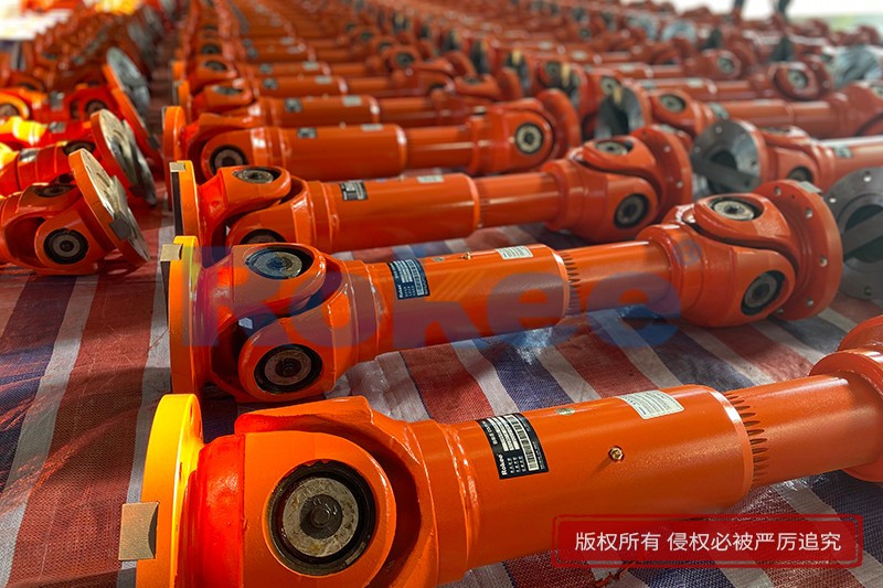
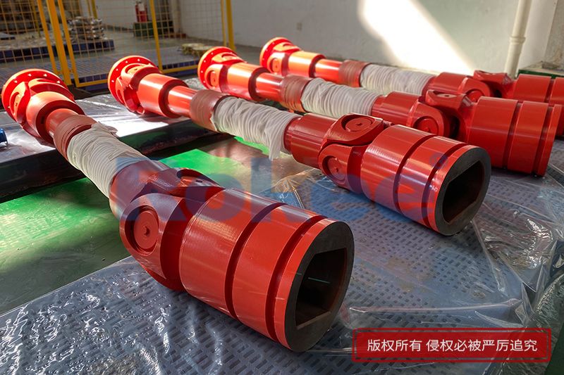
Rokee Cardan Shafts are widely used and have many impressive records. From micro products for modern logistics, artificial intelligence machinery, light products used in the paper industry, high speed and high performance products for engineering and railway vehicles, to super heavy duty products used in metallurgical rolling system systems, Rokee has won us with mature products and quality Long-term trust of customers, widely exported to Europe, America and other parts of the world.
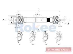
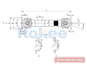
![SWC-BH Universal Coupling,Cardan Shafts]()
SWC-BH Universal Coupling
standard telescopic welded
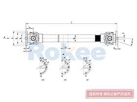
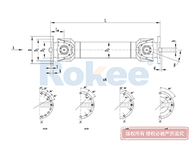
View More![SWC-CH Uuniversal Coupling,Cardan Shafts]()
SWC-CH Uuniversal Coupling
Long Telescopic Welded
View More![SWC-DH Universal Coupling,Cardan Shafts]()
SWC-DH Universal Coupling
Short Telescopic Welded
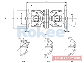
View More![SWC-WD Universal Coupling,Cardan Shafts]()
SWC-WD Universal Coupling
Non-telescopic Short
View More![SWC-WH Universal Coupling,Cardan Shafts]()
SWC-WH Universal Coupling
Non-telescopic Welded
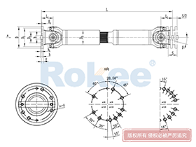
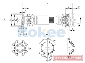
View More![SWP-A Universal Coupling,Cardan Shafts]()
SWP-A Universal Coupling
Long Type, Telescopic
View More![SWP-B Universal Coupling,Cardan Shafts]()
SWP-B Universal Coupling
Short Type, Telescopic
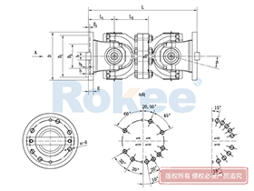
View More![SWP-C Universal Coupling,Cardan Shafts]()
SWP-C Universal Coupling
Short Type, Non-telescopic
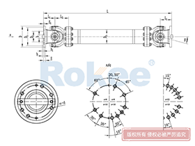
View More![SWP-D Universal Coupling,Cardan Shafts]()
SWP-D Universal Coupling
Long Type, Non-elescopic
View More
In the intricate landscape of mechanical engineering, the efficient transmission of power between non-coaxial shafts stands as a critical challenge. Among the various components designed to address this challenge, the cardan shaft emerges as a versatile and indispensable solution. Also known as a universal joint shaft, this mechanical element has played a pivotal role in advancing industrialization and mobility, enabling the seamless transfer of rotational motion and torque across misaligned axes. From the engines of automobiles to the heavy machinery in steel mills and agricultural fields, the cardan shaft’s ability to accommodate angular deviations while maintaining transmission efficiency has made it a cornerstone of modern mechanical systems.
1. Historical Evolution of the Cardan Shaft
The origins of the cardan shaft can be traced back to the exploration of mechanical flexibility in power transmission, with its design concept evolving over centuries. While the term “cardan” is attributed to the 16th-century Italian mathematician and physicist Girolamo Cardano, who extensively studied the properties of universal joints, the practical application of the cardan shaft as we know it today emerged in the 19th century. French inventor Alfred Cardan further refined the design of universal joints, laying the groundwork for the modern cardan shaft that combines these joints with a central shaft to enable efficient power transmission between misaligned components.
The industrial revolution served as a catalyst for the widespread adoption of the cardan shaft. As factories and transportation systems became more complex, the need for flexible power transmission solutions grew exponentially. Early applications included steam-powered locomotives and textile machinery, where the cardan shaft addressed the misalignment between engines and driven components. In the early 20th century, the automotive industry’s rapid development further propelled the cardan shaft’s evolution. The shift from front-engine, rear-wheel-drive configurations created a demand for components that could transmit power from the engine to the rear axle while accommodating the movement of the suspension system. This led to continuous improvements in the cardan shaft’s design, materials, and manufacturing processes, enhancing its durability and performance under varying load conditions.
2. Structural Composition and Working Principles
The cardan shaft’s ability to transmit power across misaligned axes stems from its unique structural design and the mechanical principles governing its operation. A typical cardan shaft assembly consists of three core components: universal joints (also known as cardan joints), a central shaft (or propeller shaft), and connecting yokes. Additional components, such as splined joints, lubrication fittings, and protective boots, are often incorporated to enhance flexibility, reduce wear, and extend service life.
2.1 Core Components
Universal joints are the key elements that enable angular flexibility. A basic universal joint comprises a cross-shaped intermediate member (cross shaft) with four arms, each fitted with bearings, and two U-shaped yokes attached to the input and output shafts. The cross shaft connects the two yokes, allowing the joint to bend in multiple directions. When the input shaft rotates, the cross shaft transfers rotational motion to the output yoke, even when the two shafts are not aligned. For applications requiring constant velocity transmission (such as in front-wheel-drive vehicles), double universal joints or constant velocity (CV) joints are used to eliminate speed fluctuations that occur in single universal joints at large angles.
The central shaft is the load-bearing component that transmits torque between the two universal joints. Its diameter, length, and cross-sectional design are determined by the torque requirements and the spatial constraints of the application. In some cases, the central shaft is equipped with a splined section to accommodate axial movement, allowing for adjustments in the distance between the input and output shafts. This is particularly important in automotive applications, where suspension movement can change the distance between the transmission and the axle.
Connecting yokes serve as the interface between the universal joints and the input/output shafts. They are typically bolted or welded to the shafts and feature precision-machined holes to accommodate the cross shaft bearings. The design of the yokes ensures a secure connection that can withstand high torque and rotational stress without compromising flexibility.
2.2 Working Principles
The cardan shaft operates on the principle of transferring rotational motion and torque through a series of articulated joints. When the input shaft rotates, it drives the connected yoke and cross shaft. The cross shaft’s bearings allow it to rotate freely within the yokes, enabling the output yoke to rotate even when the input and output shafts are at an angle. This angular compensation capability is the defining feature of the cardan shaft, allowing it to adapt to misalignments caused by manufacturing tolerances, component movement, or structural deflection.
However, a single universal joint has a limitation: it causes fluctuations in the output speed when the input and output shafts are misaligned. This is because the angular velocity of the output yoke varies as the cross shaft rotates, leading to a non-uniform transmission of motion. To address this issue, most cardan shaft assemblies use two universal joints arranged in a way that the speed fluctuations from the first joint are canceled out by the second. This configuration ensures constant velocity transmission, making the cardan shaft suitable for high-speed applications such as automotive driveshafts and industrial machinery.
Another key principle of the cardan shaft is its ability to accommodate axial movement. Through the use of splined joints or telescoping sections, the shaft can expand or contract to adjust for changes in the distance between the input and output components. This is crucial in applications where thermal expansion, suspension movement, or structural vibration causes axial displacement, as it prevents excessive stress on the shaft and other components.
3. Material Selection and Manufacturing Processes
The performance and durability of a cardan shaft are heavily dependent on the selection of appropriate materials and the implementation of precise manufacturing processes. Given the high torque, rotational stress, and potential exposure to harsh environments, cardan shafts require materials with excellent mechanical properties, including high tensile strength, fatigue resistance, and wear resistance. Additionally, manufacturing processes must ensure tight tolerances to maintain balance and alignment, which are critical for smooth operation and long service life.
3.1 Material Selection
High-strength alloy steels are the most commonly used materials for cardan shafts. Alloys such as 42CrMo and 40Cr are preferred due to their excellent combination of tensile strength, toughness, and fatigue resistance. These steels have a tensile strength of over 800 MPa, making them capable of withstanding the high torque and rotational stress encountered in industrial and automotive applications. The addition of alloying elements such as chromium and molybdenum enhances the material’s hardenability and wear resistance, ensuring durability under heavy load conditions.
In applications requiring lightweight design, such as high-performance vehicles or aerospace components, lightweight materials such as aluminum alloys and carbon fiber composites are increasingly being used. Carbon fiber composite shafts offer a weight reduction of up to 40% compared to steel shafts, while maintaining comparable strength and stiffness. This reduction in weight not only improves fuel efficiency but also reduces inertial forces, enhancing the overall performance of the system. However, these materials are more expensive and require specialized manufacturing processes, limiting their use to high-end applications.
For components such as universal joint bearings and cross shafts, materials with high wear resistance are essential. Case-hardened steels, which have a hard outer layer and a tough core, are commonly used for these components. The hard outer layer resists wear, while the tough core absorbs impact, preventing brittle fracture.
3.2 Manufacturing Processes
The manufacturing of a cardan shaft involves a series of precision processes, from material preparation to final assembly and testing. The key steps include material preparation, cutting, machining, heat treatment, surface treatment, assembly, and quality control.
Material preparation begins with the selection and inspection of raw materials. Suppliers provide metallurgical reports to ensure the chemical composition and mechanical properties of the materials meet the required standards. The raw materials are then cut into appropriate lengths using CNC saws, with strict control over the cutting precision to ensure the blank dimensions are within tolerance. The cut blanks are then subjected to preprocessing, such as deburring and cleaning, to remove any surface defects that could affect subsequent processes.
Machining is a critical process that determines the dimensional accuracy of the cardan shaft components. CNC lathes and milling machines are used to shape the central shaft, yokes, and other components. Precision machining ensures that the shaft’s diameter, concentricity, and surface roughness meet the design requirements. For splined sections, specialized milling or broaching processes are used to create the precise tooth profiles needed for smooth axial movement and torque transmission.
Heat treatment is essential to enhance the mechanical properties of the materials. Processes such as quenching and tempering (調質) are used to improve the strength and toughness of the central shaft and yokes. The components are heated to a high temperature (typically 850-900℃) and then rapidly cooled in oil or water to form a hard martensitic structure. They are then tempered at a lower temperature (550-600℃) to reduce internal stress and improve toughness. For components requiring high wear resistance, such as cross shafts, surface hardening processes such as carburizing or induction hardening are used to create a hard outer layer.
Surface treatment processes are applied to protect the cardan shaft from corrosion and wear. Common treatments include phosphating, which forms a protective layer that enhances paint adhesion, and electroplating (such as hard chrome plating) for components requiring high wear resistance. In harsh environments, epoxy coatings are used to provide additional corrosion protection. These coatings are cured at high temperatures to ensure durability.
Assembly involves fitting the universal joints, central shaft, and other components together. The cross shafts are fitted with bearings and lubricated to ensure smooth rotation. The yokes are bolted or welded to the central shaft, with precise alignment to ensure the universal joints operate correctly. Finally, protective boots are installed to prevent dirt and moisture from entering the joints, which could cause premature wear.
Quality control is conducted throughout the manufacturing process to ensure the cardan shaft meets the design specifications. Dimensional inspections are performed using coordinate measuring machines (CMM) to verify the accuracy of key dimensions. Non-destructive testing, such as ultrasonic or magnetic particle testing, is used to detect internal defects in the components. Dynamic balance testing is also critical, as an unbalanced cardan shaft can cause vibration, noise, and premature failure. The final assembly is tested to ensure the unbalance is within the acceptable limit (typically ≤10g·cm).
4. Applications of the Cardan Shaft
The cardan shaft’s versatility and ability to transmit power across misaligned axes make it suitable for a wide range of applications, spanning automotive, industrial, agricultural, marine, and aerospace sectors. Each application has unique requirements, leading to variations in the cardan shaft’s design, size, and material selection.
4.1 Automotive Industry
The automotive industry is one of the largest users of cardan shafts. In front-engine, rear-wheel-drive vehicles, the cardan shaft transmits power from the transmission to the rear axle, accommodating the movement of the suspension system. In four-wheel-drive and all-wheel-drive vehicles, multiple cardan shafts are used to distribute power to all four wheels. The cardan shaft in automotive applications must be lightweight, durable, and capable of withstanding high torque and rapid acceleration. To ensure constant velocity transmission, modern vehicles often use CV joints at the ends of the cardan shaft, eliminating speed fluctuations and providing a smooth ride.
In commercial vehicles such as trucks and buses, cardan shafts are designed to handle higher torque loads. They are often larger in diameter and made from high-strength alloy steels to withstand the heavy loads encountered in long-haul transportation. The cardan shafts in these vehicles also feature robust lubrication systems to ensure reliable operation under extended use.
4.2 Industrial Machinery
Industrial machinery relies heavily on cardan shafts for power transmission in various applications. In steel mills, cardan shafts are used in rolling mills to transmit power from the motor to the rolling stands, accommodating the misalignment caused by the heavy loads and thermal expansion of the equipment. In paper mills, they are used in high-speed paper machines to drive the rollers, ensuring smooth and continuous production. Other industrial applications include mining machinery, where cardan shafts transmit power to conveyors and crushers, and textile machinery, where they enable the precise movement of spinning and weaving equipment.
Industrial cardan shafts are often custom-designed to meet the specific requirements of each application. They may feature longer central shafts for large machinery or specialized joints to accommodate extreme angular misalignments. The ability to handle high torque and operate in harsh environments (such as high temperatures, dust, and moisture) is critical for industrial cardan shafts.
4.3 Agricultural Machinery
Agricultural machinery, such as tractors and harvesters, uses cardan shafts to transmit power from the tractor’s engine to various attachments, such as plows, mowers, and balers. These applications require cardan shafts that can accommodate the frequent angular changes caused by the uneven terrain and the movement of the attachments. Agricultural cardan shafts are typically designed with a high angular compensation capability and robust protective covers to prevent damage from debris and dirt.
In addition, agricultural cardan shafts often feature a power take-off (PTO) design, which allows for quick and easy connection to different attachments. The ability to withstand shock loads, such as those encountered when a plow hits a rock, is also essential for agricultural cardan shafts.
4.4 Marine and Aerospace Applications
In the marine industry, cardan shafts are used in ship propulsion systems to transmit power from the engine to the propeller. They must be capable of accommodating the misalignment between the engine and the propeller shaft, which can be caused by the ship’s hull flexing during operation. Marine cardan shafts are made from corrosion-resistant materials, such as stainless steel or alloy steels with specialized coatings, to withstand the harsh marine environment.
In aerospace applications, cardan shafts are used in aircraft engines and auxiliary power units (APUs). These applications require lightweight and high-precision cardan shafts, often made from titanium alloys or carbon fiber composites, to reduce weight and improve fuel efficiency. The cardan shafts in aerospace systems must also meet strict safety standards, as any failure could have catastrophic consequences.
5. Maintenance and Troubleshooting of Cardan Shafts
Proper maintenance is essential to ensure the reliable operation and long service life of cardan shafts. Neglecting maintenance can lead to premature wear, vibration, noise, and ultimately, component failure. The key maintenance practices include lubrication, inspection, and balancing. Additionally, timely troubleshooting of common issues can prevent minor problems from escalating into major failures.
5.1 Maintenance Practices
Lubrication is the most critical maintenance task for cardan shafts. The universal joints and bearings require regular lubrication to reduce friction and wear. The type of lubricant used depends on the application and operating conditions. For most applications, high-temperature grease with excellent anti-wear properties is recommended. The lubrication interval varies depending on the operating environment: in clean, low-temperature environments, lubrication may be required every 5,000 to 10,000 operating hours; in harsh environments, such as dusty or high-temperature settings, lubrication may be needed every 1,000 to 2,000 hours. It is also important to ensure that the lubricant is applied correctly, filling the joints completely to prevent dry spots.
Regular inspection is another key maintenance practice. Visual inspections should be conducted to check for signs of wear, such as cracks in the yokes, damage to the protective boots, or leakage of lubricant. The cardan shaft should also be checked for proper alignment and tightness of the connecting bolts. If any signs of wear or damage are detected, the component should be repaired or replaced immediately to prevent failure.
Dynamic balancing is essential for cardan shafts operating at high speeds. An unbalanced shaft can cause vibration, which not only affects the comfort of the operator (in automotive applications) but also leads to premature wear of bearings and other components. If vibration is detected, the cardan shaft should be rebalanced using specialized equipment. Rebalancing involves adding or removing small weights from the shaft to ensure uniform rotation.
5.2 Troubleshooting Common Issues
Common issues with cardan shafts include noise, vibration, and failure of the universal joints. Noise, such as a clicking or clunking sound, is often caused by worn universal joint bearings or insufficient lubrication. If the noise occurs during acceleration or deceleration, it may indicate a problem with the splined joint. Vibration is typically caused by an unbalanced shaft, misalignment, or a bent central shaft. A bent shaft can occur due to impact loads, such as hitting a pothole in automotive applications or a rock in agricultural applications.
To troubleshoot these issues, a systematic approach is recommended. First, the cardan shaft should be inspected for visual signs of damage. Then, the alignment of the input and output shafts should be checked using precision tools. If alignment is correct, the shaft should be rebalanced. If the issue persists, the universal joints should be disassembled and inspected for wear. Worn bearings or cross shafts should be replaced, and the joints should be properly lubricated before reassembly.
6. Future Developments and Trends
As technology advances, the cardan shaft continues to evolve to meet the changing needs of various industries. The key trends in the development of cardan shafts include lightweight design, improved efficiency, smart monitoring, and customization.
Lightweight design is a major focus, driven by the need to improve fuel efficiency in automotive and aerospace applications. The use of advanced materials such as carbon fiber composites and titanium alloys is expected to increase, as these materials offer significant weight reduction without compromising strength. Additionally, new manufacturing processes, such as additive manufacturing (3D printing), are being explored to create complex, lightweight designs that are difficult to achieve with traditional machining methods.
Improving transmission efficiency is another important trend. Researchers are developing new lubricants with lower friction coefficients to reduce energy loss in the universal joints. Additionally, advances in bearing technology, such as the use of ceramic bearings, are expected to further reduce friction and wear, improving the overall efficiency of the cardan shaft.
Smart monitoring is becoming increasingly important in industrial and automotive applications. The integration of sensors into cardan shafts allows for real-time monitoring of temperature, vibration, and torque. This data can be used to predict potential failures, enabling proactive maintenance and reducing downtime. In automotive applications, this technology can also be integrated with the vehicle’s electronic control unit (ECU) to optimize performance and improve safety.
Customization is another growing trend, as industries require cardan shafts tailored to specific applications. Advances in computer-aided design (CAD) and simulation software allow for the rapid design and testing of custom cardan shafts, ensuring they meet the exact requirements of each application. This customization includes variations in size, material, and joint design, enabling the cardan shaft to operate efficiently in a wide range of environments.
7. Conclusion
The cardan shaft is a fundamental component in mechanical power transmission, enabling the efficient transfer of rotational motion and torque between non-coaxial shafts. Its unique design, which combines universal joints with a central shaft, provides the flexibility to accommodate angular misalignments and axial movement, making it indispensable in a wide range of applications, from automotive and industrial machinery to agricultural and aerospace systems. The selection of appropriate materials and the implementation of precise manufacturing processes are critical to ensuring the cardan shaft’s performance and durability.
Proper maintenance, including regular lubrication, inspection, and balancing, is essential to extend the service life of cardan shafts and prevent premature failure. As technology advances, the cardan shaft continues to evolve, with trends focusing on lightweight design, improved efficiency, smart monitoring, and customization. These developments will ensure that the cardan shaft remains a vital component in mechanical systems for years to come, supporting the continued advancement of industrialization and mobility.
« Cardan Shafts » Post Date: 2023/12/26
URL: //5008517517.com/en/tags/cardan-shafts.html