Universal Shafts
Rokee is Universal Shafts Manufacturer, Customizable according to the universal shafts drawings provided by the customer, Support Export.
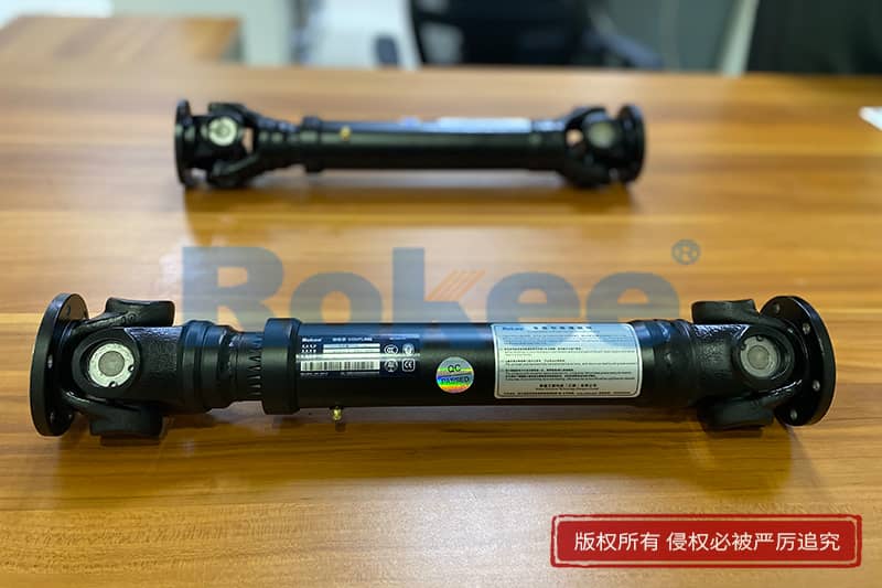
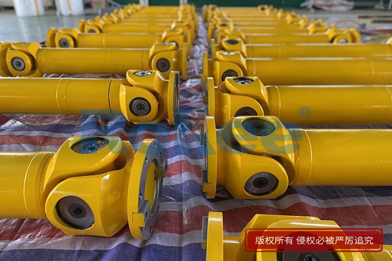
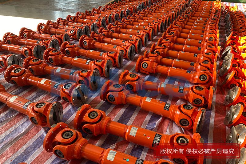
Our Universal Shafts are widely used and have many impressive records. From micro products for modern logistics, artificial intelligence machinery, light products used in the paper industry, high speed and high performance products for engineering and railway vehicles, to super heavy duty products used in metallurgical rolling system systems, Rokee has won us with mature products and quality Long-term trust of customers, widely exported to Europe, America and other parts of the world.
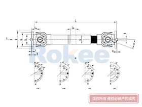
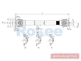
![SWC-BH Universal Coupling,Universal Shafts]()
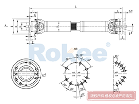
SWC-BH Universal Coupling
standard telescopic welded
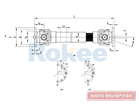
View More![SWC-CH Uuniversal Coupling,Universal Shafts]()
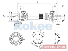
SWC-CH Uuniversal Coupling
Long Telescopic Welded
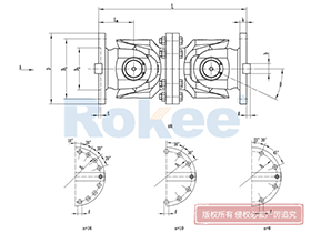
View More![SWC-DH Universal Coupling,Universal Shafts]()
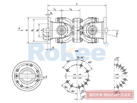
SWC-DH Universal Coupling
Short Telescopic Welded
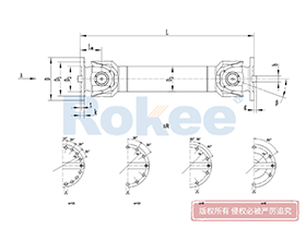
View More![SWC-WD Universal Coupling,Universal Shafts]()
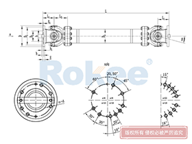
SWC-WD Universal Coupling
Non-telescopic Short
View More![SWC-WH Universal Coupling,Universal Shafts]()
SWC-WH Universal Coupling
Non-telescopic Welded
View More![SWP-A Universal Coupling,Universal Shafts]()
SWP-A Universal Coupling
Long Type, Telescopic
View More![SWP-B Universal Coupling,Universal Shafts]()
SWP-B Universal Coupling
Short Type, Telescopic
View More![SWP-C Universal Coupling,Universal Shafts]()
SWP-C Universal Coupling
Short Type, Non-telescopic
View More![SWP-D Universal Coupling,Universal Shafts]()
SWP-D Universal Coupling
Long Type, Non-elescopic
View More
In the intricate network of modern mechanical systems, the ability to transmit power reliably between non-coaxial shafts stands as a fundamental requirement. From the rolling mills of steel plants to the drive trains of automobiles, from marine propulsion systems to precision industrial machinery, there exists a component that silently bridges the gap between misaligned axes, ensuring seamless torque transfer and operational stability. This unsung hero of mechanical engineering is the universal shaft, also known as the cardan shaft. Though often overshadowed by more prominent machine components, the universal shaft plays an indispensable role in powering industries and enabling the functionality of countless devices we rely on.
At its core, the universal shaft is a mechanical component designed to connect two shafts that are not aligned on the same axis, facilitating the transmission of rotational motion and torque while accommodating angular, radial, and axial misalignments. The evolution of the universal shaft can be traced back centuries, with early conceptual designs appearing in manuscripts as early as the 13th century. However, it was the systematic refinement of its design and principles that solidified its place in modern engineering. Unlike rigid couplings that require precise alignment, the universal shaft’s unique structural design endows it with flexibility, making it suitable for applications where shaft misalignment is inevitable due to installation constraints, operational vibrations, or structural deformation.
Structural Characteristics of Universal Shafts
The basic structure of a universal shaft is composed of key components that work in tandem to achieve flexible power transmission. While specific designs may vary based on application requirements, the fundamental structure typically includes universal joints (also referred to as U-joints), a central shaft, yokes (or forks), and bearing assemblies. Each component plays a distinct role in ensuring the overall performance and reliability of the shaft.
Universal joints are the core functional components that enable angular deflection. The most common type of universal joint is the cross-shaft universal joint, which consists of a cross-shaped shaft (cross trunnion) and four bearing assemblies. The cross trunnion’s four arms are fitted with bearings, which are then mounted within the yokes attached to the driving and driven shafts. This configuration allows the yokes to rotate relative to each other around the cross trunnion, accommodating angular misalignment between the two shafts. Another widely used type is the ball cage universal joint, which features a spherical cage containing steel balls arranged in specific ball tracks. The ball cage ensures that the steel balls remain in constant contact with both the inner and outer races, enabling smooth torque transmission even at high speeds and large angular deflections. Compared to cross-shaft universal joints, ball cage designs offer superior rotational stability and are less prone to vibration at high speeds.
The central shaft, also known as the intermediate shaft, serves as the connecting link between the two universal joints. Its length and diameter are determined based on the distance between the driving and driven shafts and the torque requirements of the application. Materials used for the central shaft are typically high-strength steels, such as forged 35CrMo, which offer excellent tensile strength, fatigue resistance, and wear resistance. In some specialized applications, lightweight materials like aluminum alloys or composite materials (such as carbon fiber-reinforced polymers) may be used to reduce weight while maintaining structural integrity.
Yokes are the components that connect the universal shaft to the driving and driven shafts. They are usually forged or machined to ensure a secure fit and high structural strength. The design of the yoke must match the type of universal joint and the connection method of the shafts, which may include flange connections, spline connections, or keyway connections. Bearing assemblies, which are integrated into the universal joints, reduce friction between the moving components, ensuring smooth rotation and extending the service life of the shaft. Common bearing types used include needle bearings and roller bearings, which are selected based on the load capacity and rotational speed requirements.
Working Principles of Universal Shafts
The primary function of a universal shaft is to transmit rotational motion and torque between two non-coaxial shafts. The working principle of the universal shaft is rooted in the geometric characteristics of its universal joints, which allow for relative rotation between the connected shafts while maintaining torque transfer.
For a single cross-shaft universal joint, when the driving shaft rotates, it drives one of the yokes, which in turn rotates the cross trunnion. The cross trunnion then transmits the rotational motion to the other yoke, which drives the driven shaft. However, a key characteristic of a single universal joint is that it causes a fluctuation in the rotational speed of the driven shaft when there is an angular misalignment between the driving and driven shafts. This phenomenon, known as angular velocity fluctuation, occurs because the effective radius of the yoke arms changes as the joint rotates, leading to variations in the driven shaft’s speed even if the driving shaft rotates at a constant speed. The magnitude of this fluctuation increases with the angle of misalignment, making single universal joints unsuitable for applications requiring high rotational precision.
To address the issue of angular velocity fluctuation, a double universal shaft configuration is commonly used. This configuration consists of two universal joints connected by a central shaft. For the double universal shaft to eliminate speed fluctuation, two conditions must be met: first, the angles between the driving shaft and the central shaft must be equal to the angle between the central shaft and the driven shaft; second, the yokes at both ends of the central shaft must be aligned in the same plane. When these conditions are satisfied, the speed fluctuations caused by each universal joint cancel each other out, resulting in a constant rotational speed of the driven shaft. This makes double universal shafts ideal for applications such as automotive drive trains and industrial machinery where smooth power transmission is critical.
Ball cage universal joints operate on a slightly different principle. The spherical cage ensures that the steel balls are always positioned at the intersection of the planes perpendicular to the driving and driven shafts, regardless of the angular misalignment. This geometric arrangement ensures that the torque is transmitted evenly through the steel balls, eliminating angular velocity fluctuation even in a single joint configuration. As a result, ball cage universal joints are widely used in high-speed applications such as automotive front-wheel drive systems and precision machine tools.
Classification of Universal Shafts
Universal shafts can be classified into various types based on different criteria, including structural characteristics, transmission mode, load capacity, and application requirements. This classification helps in selecting the appropriate universal shaft for specific operating conditions.
Based on structural characteristics, universal shafts are primarily divided into cross-shaft type, ball cage type, and ball fork type. Cross-shaft universal shafts are the most widely used due to their simple structure, high load capacity, and low manufacturing cost. They are commonly found in heavy-duty applications such as engineering machinery and metallurgical equipment. Ball cage universal shafts, as mentioned earlier, offer smooth transmission and high-speed performance, making them suitable for automotive and precision industrial applications. Ball fork type universal shafts use a fork-shaped structure with steel balls, offering similar advantages to ball cage types but with a more compact design, making them ideal for applications with limited installation space.
Based on transmission mode, universal shafts can be categorized into rigid and flexible types. Rigid universal shafts are made of high-strength metal materials and are designed to transmit large torques. They have limited elasticity and are primarily used in applications where high torque transmission is the primary requirement, such as rolling mills and mining machinery. Flexible universal shafts, on the other hand, incorporate elastic materials such as rubber or plastic into their design. These materials provide damping and shock absorption capabilities, reducing vibration and noise during operation. Flexible universal shafts are commonly used in automotive applications and light-duty industrial machinery where noise reduction is important.
Based on load capacity, universal shafts can be divided into light-duty, medium-duty, heavy-duty, and extra-heavy-duty types. Light-duty universal shafts are used in applications with small torque requirements, such as small fans, pumps, and woodworking machinery. Medium-duty shafts are suitable for applications like compressors and small section mills. Heavy-duty shafts are designed for high-torque applications such as paper machines, ship drives, and medium section mills. Extra-heavy-duty shafts are used in extremely demanding conditions, such as crushers, thick plate shears, and large rolling mills, where they can transmit torques exceeding 10,000 kNm.
Additionally, universal shafts can be classified based on their length compensation capability. Telescopic universal shafts are equipped with spline connections that allow for axial movement, accommodating changes in the distance between the driving and driven shafts due to thermal expansion or structural deformation. Fixed-length universal shafts, on the other hand, do not have length compensation and are used in applications where the shaft distance is constant.
Industrial Applications of Universal Shafts
The versatility and reliability of universal shafts make them indispensable in a wide range of industrial sectors. From heavy industry to precision manufacturing, from transportation to energy production, universal shafts play a critical role in ensuring the smooth operation of various mechanical systems.
The metallurgical industry is one of the primary users of universal shafts, particularly in rolling mills, piercing machines, and straightening machines. These applications require the transmission of extremely large torques under harsh conditions, including high temperatures, heavy vibrations, and significant shaft misalignments. Heavy-duty cross-shaft universal shafts are commonly used in these systems, as they can withstand the high stress and ensure reliable power transmission. For example, in a hot rolling mill, universal shafts connect the motor to the rolling stands, transmitting the torque required to deform the steel billets into sheets or bars.
The automotive industry is another major application area for universal shafts. In rear-wheel drive and four-wheel drive vehicles, universal shafts (known as drive shafts) transmit torque from the transmission to the rear axle or front axles. Due to the dynamic nature of vehicle operation, the distance and angle between the transmission and axles change as the vehicle moves over uneven terrain or when the suspension compresses and extends. Universal shafts with telescopic and angular compensation capabilities are essential to accommodate these changes, ensuring smooth power delivery to the wheels. Ball cage universal shafts are widely used in front-wheel drive vehicles due to their high-speed performance and compact design.
The marine industry relies on universal shafts for ship propulsion systems. Ships often have complex propulsion configurations, with the engine and propeller shafts rarely aligned perfectly. Universal shafts are used to connect the engine to the gearbox and the gearbox to the propeller, accommodating the angular misalignments and ensuring efficient torque transmission. In addition, universal shafts are used in various auxiliary systems on ships, such as pumps, winches, and steering mechanisms.
The industrial machinery sector, which includes equipment such as paper machines, mining machinery, and cement kilns, also heavily utilizes universal shafts. Paper machines, for example, require precise and smooth power transmission to ensure consistent paper quality. Universal shafts are used to connect the various sections of the paper machine, such as the forming section, pressing section, and drying section, accommodating the misalignments caused by the machine’s large size and structural deformation. In mining machinery, such as crushers and conveyors, universal shafts transmit large torques in dusty and harsh environments, requiring high durability and low maintenance.
Other application areas include agricultural machinery, where universal shafts are used in tractors and harvesters to transmit power to various attachments; aerospace, where lightweight and high-precision universal shafts are used in aircraft engines and control systems; and renewable energy, such as wind turbines, where universal shafts help transmit power from the rotor to the generator.
Selection Criteria for Universal Shafts
Selecting the appropriate universal shaft for a specific application is critical to ensuring optimal performance, reliability, and cost-effectiveness. The selection process involves considering several key factors, including load characteristics, rotational speed, axis misalignment, installation space, and environmental conditions.
Load characteristics are the primary consideration when selecting a universal shaft. The type of load (steady load, light impact load, medium impact load, or heavy impact load) and the magnitude of the torque must be carefully evaluated. Different types of universal shafts have different torque-carrying capacities, and selecting a shaft that cannot withstand the required torque will result in premature failure. The working condition factor (K) is often used to calculate the equivalent torque, taking into account the impact and fluctuation of the load. For example, a crusher operates under heavy impact loads, requiring a universal shaft with a high torque capacity and robust construction, while a centrifugal pump operates under steady loads, allowing for a lighter-duty shaft.
Rotational speed is another important factor. The maximum allowable speed of a universal shaft is determined by its design, material, and balance quality. High-speed applications, such as automotive drive shafts or precision machine tools, require universal shafts with high dynamic balance precision to minimize vibration and noise. The dynamic balance precision is typically specified by grades such as G6.3 or G16, with lower grades indicating higher precision. For shafts with a rotational diameter of 390 mm or less, the maximum speed must be checked to ensure it does not exceed the allowable limit. If the linear speed exceeds 7 m/s, a higher dynamic balance precision is usually required.
Axis misalignment, including angular misalignment, radial misalignment, and axial misalignment, must be considered when selecting the type of universal shaft. Different types of universal shafts have different misalignment compensation capabilities. Cross-shaft universal shafts can typically accommodate angular misalignments between 5° and 45°, while ball cage universal shafts can handle larger angular misalignments up to 45° or more. The actual misalignment in the application must be within the range specified by the universal shaft’s manufacturer to ensure proper operation and avoid excessive wear.
Installation space constraints also play a role in the selection process. In applications with limited space, such as automotive front-wheel drive systems or compact industrial machinery, compact universal shaft designs, such as ball cage or ball fork types, are preferred. Additionally, the length of the central shaft and the type of connection (flange, spline, etc.) must be compatible with the available installation space.
Environmental conditions, such as temperature, humidity, dust, and corrosive substances, can affect the performance and service life of universal shafts. High-temperature environments, such as those in metallurgical mills, require universal shafts made of heat-resistant materials with appropriate lubrication. Corrosive environments, such as marine or chemical processing facilities, require shafts with corrosion-resistant coatings or materials. Dust and debris can cause wear on the bearing assemblies, so sealed universal shafts or those with effective dust protection should be selected for such environments.
Other factors to consider include the shaft’s length compensation requirement, the type of lubrication (grease-lubricated, oil-lubricated, or maintenance-free), and the ease of installation and maintenance. By carefully evaluating these factors, engineers can select the most suitable universal shaft for their specific application.
Maintenance Practices for Universal Shafts
Proper maintenance is essential to extend the service life of universal shafts, reduce downtime, and ensure safe operation. Maintenance practices for universal shafts include regular inspection, lubrication, alignment checks, and component replacement.
Regular inspection is the foundation of effective maintenance. Inspections should be conducted to check for signs of wear, damage, or looseness in the universal joints, central shaft, yokes, and bearing assemblies. Common signs of wear include abnormal noise during operation, vibration, leakage of lubricant, and excessive play in the universal joints. For example, if a universal joint produces a clicking or clunking sound when the shaft rotates, it may indicate worn bearings or a damaged cross trunnion. Regular inspections can help identify these issues early, preventing more serious damage to the shaft or other components.
Lubrication is critical to reducing friction between the moving components of the universal shaft. Proper lubrication ensures smooth rotation, reduces wear, and prevents corrosion. The type of lubricant (grease or oil) and the lubrication interval depend on the universal shaft’s design and operating conditions. Grease-lubricated universal shafts are more common in industrial applications, while oil-lubricated shafts are used in high-speed or high-temperature applications. It is important to follow the manufacturer’s recommendations for lubricant type and replacement interval. Over-lubrication or under-lubrication can both lead to premature failure; over-lubrication can cause excessive pressure, while under-lubrication can result in dry friction and overheating.
Alignment checks are essential to ensure that the universal shaft is operating within the specified misalignment limits. Misalignment beyond the allowable range can cause excessive stress on the universal joints and bearings, leading to increased wear and vibration. Alignment checks should be conducted during installation and periodically during operation, especially after any maintenance or structural changes to the equipment. Various tools, such as laser alignment tools or dial indicators, can be used to measure the angular and radial misalignments between the driving and driven shafts.
Component replacement is necessary when parts are worn or damaged beyond repair. Common components that need replacement include bearings, seals, cross trunnions, and yokes. When replacing components, it is important to use parts that are compatible with the universal shaft’s design and specifications. Improperly sized or low-quality components can compromise the performance and safety of the shaft. Additionally, after replacing components, the universal shaft should be re-aligned and lubricated to ensure proper operation.
Future Development Trends of Universal Shafts
As technology advances and industrial requirements become more demanding, the universal shaft is continuously evolving to meet new challenges. Several key trends are shaping the future development of universal shafts, including the use of advanced materials, design optimization, intelligent monitoring, and environmental sustainability.
The use of advanced materials is one of the primary trends in universal shaft development. Traditional universal shafts are mostly made of steel, but there is a growing demand for lightweight materials to reduce energy consumption and improve performance. Composite materials, such as carbon fiber-reinforced polymers (CFRP), offer high strength-to-weight ratios, making them ideal for applications where weight reduction is critical, such as aerospace and automotive. Additionally, advanced alloys with improved heat resistance and corrosion resistance are being developed for use in harsh environments, such as high-temperature metallurgical processes and marine applications.
Design optimization through simulation and modeling is another important trend. With the development of finite element analysis (FEA) and computational fluid dynamics (CFD) tools, engineers can simulate the performance of universal shafts under various operating conditions, optimizing their design for maximum strength, minimum weight, and improved fatigue life. This allows for the development of more efficient and reliable universal shafts that can withstand higher torques and speeds while reducing material usage and manufacturing costs.
Intelligent monitoring and predictive maintenance are becoming increasingly common in industrial equipment, and universal shafts are no exception. Sensors embedded in the universal shaft can monitor parameters such as temperature, vibration, and torque in real time, providing data on the shaft’s operating condition. This data can be analyzed using machine learning algorithms to detect early signs of wear or damage, allowing for predictive maintenance before a failure occurs. This not only reduces downtime but also extends the service life of the universal shaft and reduces maintenance costs.
Environmental sustainability is also driving the development of universal shafts. There is a growing focus on reducing the environmental impact of manufacturing processes, including the use of recyclable materials and the reduction of energy consumption. Additionally, maintenance-free or low-maintenance universal shafts are being developed to reduce the use of lubricants, which can be harmful to the environment if not properly disposed of.
Finally, the integration of universal shafts with other advanced technologies, such as electric drives and autonomous systems, is opening up new application areas. For example, in electric vehicles, the demand for high-efficiency and compact universal shafts is increasing as manufacturers strive to maximize the range and performance of the vehicles. In autonomous industrial machinery, universal shafts with intelligent monitoring capabilities are essential to ensure reliable operation without human intervention.
Conclusion
The universal shaft is a critical component in modern mechanical systems, enabling reliable power transmission between non-coaxial shafts across a wide range of industries. Its unique structural design and flexible working principle make it indispensable in applications where shaft misalignment is inevitable, from heavy metallurgical mills to precision automotive drive trains. Understanding the structural characteristics, classification, and application requirements of universal shafts is essential for selecting the appropriate type for a specific application, while proper maintenance practices ensure their long-term reliability and performance.
As technology continues to advance, the universal shaft is evolving to meet the growing demands of modern industry. The use of advanced materials, design optimization, intelligent monitoring, and environmental sustainability are shaping the future of universal shaft development, leading to more efficient, reliable, and eco-friendly components. Despite being a relatively simple component compared to many modern mechanical systems, the universal shaft will continue to play a vital role in powering the industries of the future, proving that even the most basic components can have a profound impact on the functionality and efficiency of complex machinery.
« Universal Shafts » Post Date: 2024/1/16
URL: //5008517517.com/en/tags/universal-shafts.html