Tooth Gear Couplings
Rokee is Tooth Gear Couplings Manufacturer, Customizable according to the tooth gear couplings drawings provided by the customer, Support Export.
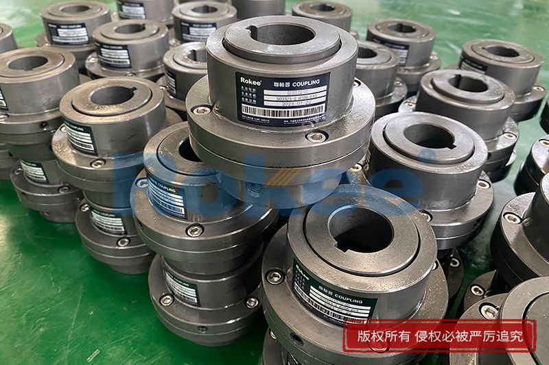
Tooth Gear Coupling can be applied into various general drive sites. Due to the special hook face drum gear design, in the definitive deviation scope, Tooth Gear Coupling can effectively avoid the edge stress concentration at tooth meshing, so Tooth Gear Coupling has outstanding radial and angular centering capacity. Moreover, Tooth Gear Coupling can ensure long service life.
![RODX Drum Gear Coupling,Tooth Gear Couplings]()
RODX Drum Gear Coupling
Intermediate Connecting Shaft
RODX Drum Gear Coupling is an extended type of ROD series coupling with a floating shaft design in the middle, suitable for increasing transmission distance.View More![RODP Drum Gear Coupling,Tooth Gear Couplings]()
RODP Drum Gear Coupling
With Brake Discs
The RODP Drum Gear Coupling is a type of ROD series coupling with a brake disc, suitable for transmission situations where braking needs to be used in conjunction with disc brakes.View More![RODF Drum Gear Coupling,Tooth Gear Couplings]()
RODF Drum Gear Coupling
Split Type, Brake Disc
The RODF Drum Gear Coupling is a type of ROD series coupling with split brake discs, suitable for transmission situations where there is braking demand and the braking position changes when used in conjunction with disc brakes.View More![RODW Drum Gear Coupling,Tooth Gear Couplings]()
RODW Drum Gear Coupling
With Brake Wheel
The RODW Drum Gear Coupling is a type of ROD series coupling with brake wheels, suitable for transmission situations where braking needs to be used in conjunction with wheel brakes.View More![RODU Drum Gear Coupling,Tooth Gear Couplings]()
RODU Drum Gear Coupling
With Brake Wheel
The RODU Drum Gear Coupling is another type of ROD series coupling with brake wheels, suitable for transmission situations where braking needs to be used in conjunction with wheel brakes and applied to one end of the axle, achieving smoother and more reliable braking performance.View More![RODV Drum Gear Coupling,Tooth Gear Couplings]()
RODV Drum Gear Coupling
Vertical Installation
The RODV Drum Gear Coupling is a vertical installation type of the ROD series coupling, suitable for transmission situations that require vertical transmission torque.View More![RODM Drum Gear Coupling,Tooth Gear Couplings]()
RODM Drum Gear Coupling
Torsion Protection
The RODM Drum Gear Coupling is a torque setting form of the ROD series coupling. By adjusting relevant components, the maximum transmission torque can be easily set within a certain range. Suitable for shafting transmission situations that require safe torque operation to protect important machine components from excessive damage.View More![GICL Drum Gear Coupling,Tooth Gear Couplings]()
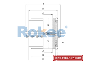
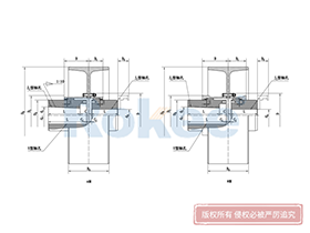
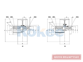
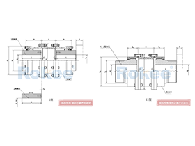
GICL Drum Gear Coupling
Wide
GICL Drum Gear Coupling has larger inner teeth width, which can transfer torque while compensating for larger axial displacement.View More![GICLZ Drum Gear Coupling,Tooth Gear Couplings]()
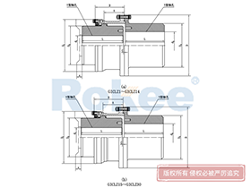
GICLZ Drum Gear Coupling
Connected to Intermediate Shaft
Half of the GICLZ Drum Gear Coupling adopts a non-toothed semi-coupling sleeve structure, which is usually connected in pairs or used in occasions with small angular displacement.View More![GIICL Drum Gear Coupling,Tooth Gear Couplings]()
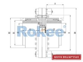
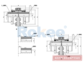
GIICL Drum Gear Coupling
Narrow
GIICL Drum Gear Coupling has small inner teeth width, which can transfer torque while compensating for small axial displacement. Also, its structure is compact and the moment of inertia is low.View More![GIICLZ Drum Gear Coupling,Tooth Gear Couplings]()
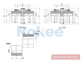
GIICLZ Drum Gear Coupling
Connected to Intermediate Shaft
Half of the GIICLZ Drum Gear Coupling adopts a non-toothed semi-coupling sleeve structure, which is usually connected in pairs or used in occasions with small angular displacement. Also, its structure is compact and the moment of inertia is low.View More![GCLD Drum Gear Coupling,Tooth Gear Couplings]()
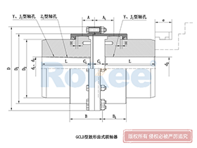
GCLD Drum Gear Coupling
Motor Shaft Extension
GCLD Drum Gear Coupling is generally used for direct connection with the motor, so it generally has a higher speed and compact structure.View More![NGCL Drum Gear Coupling,Tooth Gear Couplings]()
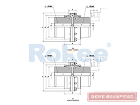
NGCL Drum Gear Coupling
With Brake Wheel
NGCL Drum Gear Coupling is designed with a brake wheel, suitable for situations where braking is required.View More![NGCLZ Drum Gear Coupling,Tooth Gear Couplings]()
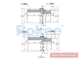
NGCLZ Drum Gear Coupling
With Brake Wheel
NGCLZ Drum Gear Coupling is designed with a brake wheel, suitable for situations where braking is required. Half of its structure adopts a semi-coupling sleeve design, with smaller angular displacement compensation but more stable braking.View More![WG Drum Gear Coupling,Tooth Gear Couplings]()
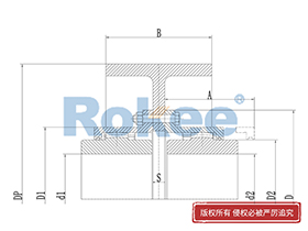
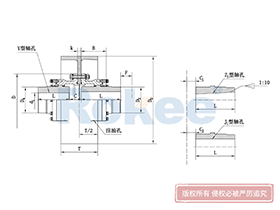
WG Drum Gear Coupling
Basic
The overall characteristics of WG Drum Gear Coupling are similar to those of other drum gear couplings, but with a larger modulus design, which can generally transmit greater torque.View More![WGZ Drum Gear Coupling,Tooth Gear Couplings]()
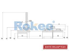
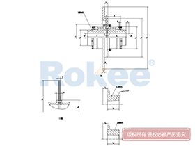
WGZ Drum Gear Coupling
With Brake Wheel
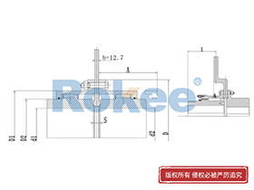
WGZ Drum Gear Coupling is designed with a brake wheel, suitable for shoe type braking.View More![WGP Drum Gear Coupling,Tooth Gear Couplings]()
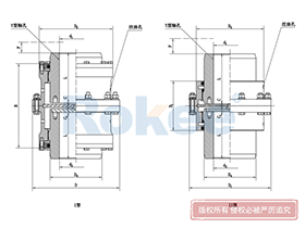
WGP Drum Gear Coupling
With Brake Discs
WGP Drum Gear Coupling is designed with a brake disc, suitable for disc type braking.View More![WGT Drum Gear Coupling,Tooth Gear Couplings]()
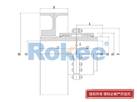
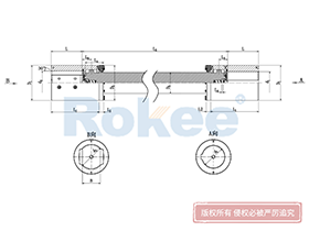
WGT Drum Gear Coupling
Intermediate Connecting Pipe
WGT Drum Gear Coupling is designed with indirect tube, suitable for long distance torque transfer.View More![WGC Drum Gear Coupling,Tooth Gear Couplings]()
WGC Drum Gear Coupling
Vertical Installation
WGC Drum Gear Coupling is specially designed for situations where vertical transmission is required, suitable for some vertical transmission systems.View More![WGJ Drum Gear Coupling,Tooth Gear Couplings]()
WGJ Drum Gear Coupling
Connected to Intermediate Shaft
WGJ Drum Gear Coupling is designed with intermediate shaft, suitable for long distance torque transmission, and some are equipped with axial buffers.View More
In the complex landscape of industrial power transmission systems, couplings serve as the critical link that bridges rotating shafts, ensuring seamless torque transfer while accommodating inevitable misalignments. Among the diverse array of coupling technologies available, tooth gear couplings stand out for their exceptional torque-carrying capacity, robust compensation capabilities, and reliability in harsh operating conditions. From heavy-duty metallurgical rolling mills to precision wind turbine gearboxes, these mechanical components play an indispensable role in sustaining the efficiency and longevity of industrial machinery.
1. Fundamental Structure and Working Principles
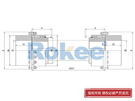
At its core, a tooth gear coupling is a type of rigid-flexible coupling designed to transmit torque between two independently supported shafts while allowing for axial, radial, and angular displacements. The basic configuration of a tooth gear coupling consists of three primary components: two externally toothed hubs (also known as half-couplings) and one internally toothed sleeve (or ring gear). The externally toothed hubs are mounted on the drive and driven shafts, typically via keyway connections, splines, or interference fits, ensuring a secure bond that prevents relative rotation between the hub and the shaft. The internally toothed sleeve acts as the floating member, meshing with the external teeth of both hubs to establish the torque transfer path.
The working principle of a tooth gear coupling is rooted in the meshing of involute gear teeth, a geometric profile widely adopted in gear design for its smooth transmission characteristics and ability to distribute loads evenly. When the drive shaft rotates, it imparts rotational motion to the attached external hub, whose teeth engage with the internal teeth of the sleeve. This meshing action transfers the torque through the sleeve to the second external hub, which in turn drives the driven shaft. A defining feature of this design is the relative sliding motion between the meshing tooth flanks when shaft misalignments occur. This sliding, while introducing a small degree of power loss and wear, enables the coupling to compensate for misalignments caused by installation errors, thermal expansion of shafts during operation, or structural deflection under load.
To ensure optimal performance, the tooth gear coupling also incorporates auxiliary components such as sealing devices and lubrication systems. Seals prevent the leakage of lubricant and block the ingress of external contaminants (e.g., dust, moisture, and industrial debris) that could accelerate tooth wear and corrosion. The lubrication system, which may include oil holes, oil passages, and grease chambers, delivers a continuous supply of lubricant to the meshing teeth. This lubricant forms a protective film between the tooth surfaces, reducing friction and wear, dissipating heat generated by sliding, and extending the service life of the coupling.
2. Key Types of Tooth Gear Couplings: Straight-Tooth vs. Curved-Tooth
Tooth gear couplings are primarily classified into two categories based on the profile of the external teeth: straight-tooth (or spur-tooth) and curved-tooth (or barrel-tooth) couplings. Each type exhibits distinct structural characteristics, performance capabilities, and application suitability, making the selection process dependent on specific operating conditions and torque requirements.
2.1 Straight-Tooth Gear Couplings
Straight-tooth gear couplings feature external teeth with a linear profile along the axial direction of the hub. This simplistic design makes them relatively easy to manufacture using standard gear-cutting processes such as hobbing or shaping, resulting in lower production costs compared to curved-tooth alternatives. The straightforward structure also facilitates easier installation and maintenance, as alignment checks and component replacement can be performed with basic tools.
However, the linear tooth profile imposes limitations on the coupling's misalignment compensation capability. When angular or radial misalignments occur, the meshing contact between the straight teeth is concentrated at the tooth ends, leading to localized stress concentrations and accelerated wear. This restricts the application of straight-tooth gear couplings to scenarios with minimal expected misalignments, typically in medium-to-low torque, low-speed applications such as small pumps, fans, and light-duty conveyors.
2.2 Curved-Tooth Gear Couplings
Curved-tooth gear couplings represent an optimized variant of the basic tooth gear design, with the external teeth machined into a spherical (barrel) profile centered on the axis of the shaft. This curved profile fundamentally improves the meshing characteristics by increasing the contact area between the external and internal teeth and distributing the load more evenly across the tooth width. Unlike straight-tooth couplings, curved-tooth designs eliminate tooth-end contact during angular misalignment, significantly reducing stress concentrations and wear rates.
The spherical tooth profile also enhances the coupling's misalignment compensation capacity. Curved-tooth gear couplings can accommodate angular displacements of up to 1.5–2 degrees (depending on the design), radial displacements of several millimeters, and axial displacements corresponding to the tooth width. Additionally, the optimized load distribution enables curved-tooth couplings to transmit 15–30% more torque than straight-tooth couplings of the same radial size, making them ideal for high-torque, heavy-duty applications. Despite these advantages, curved-tooth couplings have higher manufacturing costs due to the complex machining processes required to produce the spherical tooth profile, and they demand more precise installation to fully leverage their performance capabilities.
3. Core Performance Advantages of Tooth Gear Couplings
Tooth gear couplings have earned widespread adoption in industrial applications due to a suite of performance advantages that address the challenges of power transmission in demanding environments. These advantages include exceptional torque-carrying capacity, superior misalignment compensation, structural compactness, broad environmental adaptability, and high reliability.
3.1 High Torque-Carrying Capacity
The most prominent advantage of tooth gear couplings is their ability to transmit large torques efficiently. This capability stems from the multi-tooth meshing design, which distributes the applied load across numerous tooth surfaces simultaneously. Unlike couplings that rely on a single contact point (e.g., pin-and-bushing couplings), tooth gear couplings minimize the load per unit area on the teeth, enabling them to handle significantly higher torques without premature failure. In practical applications, tooth gear couplings outperform many other coupling types in terms of torque density (torque transmitted per unit radial size), making them the preferred choice for heavy-duty machinery such as metallurgical rolling mills, mine hoists, and large crushers.
3.2 Superior Misalignment Compensation
Shaft misalignment is an unavoidable issue in industrial power transmission systems, arising from factors such as imprecise installation, thermal expansion, shaft deflection, and foundation settlement. Uncompensated misalignment can lead to increased vibration, excessive bearing loads, and premature failure of shafts or machinery components. Tooth gear couplings excel at addressing this challenge by accommodating axial, radial, and angular misalignments simultaneously. Curved-tooth variants, in particular, offer enhanced compensation capabilities, ensuring smooth torque transmission even in applications with significant misalignments, such as large rotating equipment with flexible foundations.
3.3 Structural Compactness
Modern tooth gear couplings are designed to be structurally compact, with minimal radial dimensions relative to their torque-carrying capacity. This compactness is achieved through optimized gear tooth geometry and integrated component designs (e.g., one-piece end caps and internal gear rings for small-sized couplings). For applications with limited installation space (e.g., enclosed gearboxes, compact industrial pumps, and automotive transmissions), the small footprint of tooth gear couplings is a critical advantage. Additionally, the reduced weight associated with compact designs lowers the rotational inertia of the coupling, minimizing energy consumption and reducing the load on the drive motor and shaft bearings.
3.4 Broad Environmental Adaptability
Tooth gear couplings are capable of operating reliably in a wide range of harsh environmental conditions, thanks to flexible material selection and robust sealing designs. By using high-performance materials such as alloy steels (e.g., 20CrMnTi) subjected to heat treatments like carburizing and quenching, the couplings can withstand high temperatures, corrosion, and mechanical impact. Sealing systems, such as lip seals or labyrinth seals, protect the internal components from moisture, dust, and corrosive media, enabling the couplings to be used in marine environments, chemical plants, mining operations, and outdoor energy facilities (e.g., wind farms and hydroelectric power plants).
3.5 High Reliability and Long Service Life
When properly designed, installed, and maintained, tooth gear couplings exhibit high reliability and a long service life. The use of high-strength, wear-resistant materials and precise manufacturing processes (e.g., grinding and polishing of tooth surfaces to achieve low surface roughness, Ra ≤ 0.4 μm) ensures that the couplings can withstand the rigors of continuous industrial operation. Additionally, the even load distribution across the meshing teeth reduces the risk of premature failure due to fatigue or localized wear. In applications such as power generation and heavy manufacturing, where unplanned downtime is costly, the reliability of tooth gear couplings is a key factor in ensuring continuous production.
4. Typical Application Scenarios
The unique combination of high torque capacity, misalignment compensation, and environmental adaptability makes tooth gear couplings suitable for a diverse range of industrial applications, spanning heavy machinery, energy production, transportation, and general manufacturing. Below are some of the most common application areas:
4.1 Metallurgical Industry
The metallurgical industry, which includes steel rolling mills, continuous casting equipment, and blast furnaces, operates under extreme conditions of high torque, high temperature, and significant shaft misalignments. Tooth gear couplings are widely used in rolling mill drive systems, where they transmit the massive torques required to deform steel billets into sheets, bars, or plates. Curved-tooth couplings are particularly preferred in this sector due to their ability to compensate for the misalignments caused by the thermal expansion of rolls and the structural deflection of the mill frame.
4.2 Mining and Heavy Machinery
Mining equipment such as mine hoists, crushers, and conveyor systems relies on robust torque transmission to handle the extraction and transportation of bulk materials. Tooth gear couplings are used in the drive systems of these machines, providing the high torque capacity needed to power crushers that break down large rock formations and hoists that lift heavy loads. The couplings' ability to withstand dusty, humid, and corrosive mining environments, coupled with their reliability, makes them essential components in this industry.
4.3 Energy Production
In the energy sector, tooth gear couplings are employed in both conventional and renewable energy systems. In thermal power plants and nuclear power plants, they connect the turbines to the generators, transmitting high torques at high speeds (after dynamic balancing). In wind energy systems, they are used in gearboxes to connect the low-speed rotor shaft to the high-speed generator shaft, accommodating the misalignments caused by wind-induced vibrations and the flexing of the turbine tower. Hydroelectric power plants also use tooth gear couplings in the drive systems of water turbines, where they handle the high torques generated by the flow of water.
4.4 Transportation and Marine Engineering
Tooth gear couplings find applications in the transportation sector, particularly in heavy-duty vehicles such as trucks, buses, and locomotives, where they are used in transmission systems to connect the engine to the drive axle. In marine engineering, they are employed in ship propulsion systems, connecting the main engine to the propeller shaft. The marine environment demands couplings that can withstand saltwater corrosion and vibration, making sealed tooth gear couplings with corrosion-resistant materials an ideal choice.
4.5 General Manufacturing and Machinery
In general manufacturing, tooth gear couplings are used in a wide range of equipment, including large pumps, fans, compressors, and industrial robots. For example, in chemical plants, they connect the motors to the shafts of centrifugal pumps that handle corrosive fluids, relying on their sealed design to prevent contamination of the coupling components. In HVAC systems, they are used in large fans, providing the torque capacity needed to move large volumes of air while compensating for the misalignments in the ductwork and fan housing.
5. Design Considerations for Tooth Gear Couplings
The design of a tooth gear coupling is a complex engineering process that must take into account multiple factors, including torque requirements, shaft speeds, misalignment conditions, environmental factors, and material properties. Below are the key considerations that guide the design process:
5.1 Torque and Load Analysis
The primary design criterion for a tooth gear coupling is the maximum torque it must transmit. This requires a detailed analysis of the application's torque requirements, including nominal torque, peak torque (due to start-up or load fluctuations), and shock loads. Engineers use gear strength calculation formulas to ensure that the coupling's teeth can withstand these loads without failure. Two critical strength parameters are bending strength (to prevent tooth breakage) and contact strength (to prevent pitting or scuffing of the tooth surfaces). The bending strength is calculated using the formula: σ_F = (K F_t Y_F Y_S) / (b m), where K is the load factor, F_t is the tangential force, Y_F is the form factor, Y_S is the stress correction factor, b is the tooth width, and m is the module. The contact strength is determined using the Hertz formula: σ_H = Z_E Z_H Z_ε √[(K F_t / (b d_1)) * ((u ± 1) / u)], where Z_E is the elastic coefficient, Z_H is the zone factor, Z_ε is the contact ratio factor, d_1 is the pitch diameter of the external gear, and u is the gear ratio.
5.2 Material Selection and Heat Treatment
The choice of material for the coupling components is critical to ensuring performance and durability. Externally toothed hubs and internally toothed sleeves are typically made from high-strength alloy steels, such as 20CrMnTi, 40CrNiMoA, or 35CrMo, which offer excellent mechanical properties (strength, toughness, and wear resistance). Heat treatment processes are essential to enhance these properties: carburizing and quenching are used to achieve a hard, wear-resistant surface (HRC 58–62) and a tough core (HRC 30–45), while nitriding is preferred for high-speed applications to reduce thermal deformation and improve surface hardness. For corrosive environments, materials such as stainless steel or alloy steels with corrosion-resistant coatings may be used.
5.3 Gear Geometry Optimization
The geometry of the gear teeth, including the module, number of teeth, pressure angle, and tooth profile, is optimized to ensure smooth meshing, even load distribution, and maximum misalignment compensation. The involute tooth profile with a pressure angle of 20–25 degrees is the standard choice for tooth gear couplings, as it provides a constant transmission ratio and minimizes sliding friction. For curved-tooth couplings, the radius of the spherical tooth profile is carefully calculated to ensure that the contact area remains optimal even at maximum misalignment. Additionally, tooth end relief (or crowning) may be applied to further reduce stress concentrations at the tooth ends.
5.4 Dynamic Stability and Balancing
For high-speed applications (e.g., gas turbines, generators), dynamic stability is a critical consideration. Unbalanced rotating components can cause excessive vibration, noise, and premature wear of bearings and other machinery parts. Tooth gear couplings intended for high-speed operation undergo precision dynamic balancing to meet strict balance grades (e.g., ISO 1328 Class 4–6), ensuring that the rotating mass is evenly distributed and vibration is minimized. Engineers may also conduct dynamic analysis (e.g., modal analysis and harmonic response analysis) to identify and mitigate potential resonance issues.
5.5 Lubrication and Sealing Design
The lubrication system is designed to deliver the appropriate type and quantity of lubricant to the meshing teeth. For low-speed, heavy-load applications, grease lubrication is typically used, while high-speed applications may require forced oil lubrication to ensure adequate heat dissipation. The choice of lubricant depends on operating temperature, speed, and environmental conditions; common options include mineral oils, synthetic oils, and extreme-pressure greases. The sealing system is designed to match the lubrication type and environmental conditions, with lip seals, labyrinth seals, or mechanical seals used to prevent lubricant leakage and contaminant ingress.
6. Maintenance and Troubleshooting
Proper maintenance is essential to ensure the long-term performance and reliability of tooth gear couplings. Neglecting maintenance can lead to accelerated wear, reduced efficiency, and sudden failure, resulting in costly downtime. Below are key maintenance practices and common troubleshooting guidelines:
6.1 Routine Lubrication
Regular lubrication is the most critical maintenance task for tooth gear couplings. The frequency of lubrication depends on operating conditions (speed, load, temperature, and environment) but typically ranges from every 500 to 2000 operating hours. When re-lubricating, the old lubricant should be completely drained to remove contaminants and worn particles before refilling with fresh lubricant of the recommended type and quantity. Over-lubrication should be avoided, as it can cause excessive heat buildup and seal damage.
6.2 Regular Inspection
Routine inspections should be conducted to check for signs of wear, damage, or misalignment. Key inspection items include: (1) visual inspection of the teeth for pitting, scuffing, chipping, or excessive wear; (2) checking for lubricant leakage, which may indicate seal damage; (3) measuring vibration levels to detect misalignment or unbalance; (4) inspecting the hub-shaft connection for looseness; and (5) checking the coupling for excessive axial or radial movement. Inspections should be more frequent in harsh environments or high-load applications.
6.3 Alignment Checks and Adjustments
Although tooth gear couplings can compensate for misalignments, excessive or persistent misalignment will accelerate wear and reduce service life. Periodic alignment checks using laser alignment tools or dial indicators are recommended to ensure that the drive and driven shafts are within the coupling's misalignment limits. If misalignment exceeds the recommended limits, adjustments should be made to the motor or driven equipment mounts to correct the issue.
6.4 Common Troubleshooting
Common issues with tooth gear couplings and their solutions include:
- Excessive vibration: This is often caused by misalignment, unbalance, or worn teeth. Solutions include realigning the shafts, rebalancing the coupling, or replacing worn components.
- Lubricant contamination: Contaminated lubricant (e.g., with metal particles, dust, or moisture) indicates seal failure or excessive wear. The solution involves replacing the lubricant, inspecting and replacing damaged seals, and identifying the source of contamination.
- Tooth wear or pitting: This can be caused by insufficient lubrication, overloading, or misalignment. Solutions include improving lubrication, reducing load if possible, realigning the shafts, and replacing worn teeth or components.
- Torque loss or slipping: This is typically due to a loose hub-shaft connection. The solution involves tightening the connection (e.g., re-torquing bolts, replacing worn keys) or re-establishing the interference fit if necessary.
7. Future Trends in Tooth Gear Coupling Technology
As industrial machinery becomes more efficient, intelligent, and compact, tooth gear coupling technology is evolving to meet these changing demands. Several key trends are shaping the future of these components:
First, there is a growing focus on lightweight and compact design through the use of advanced materials and topological optimization. The adoption of composite materials (e.g., carbon fiber-reinforced polymers) and high-strength, low-weight alloys is helping to reduce the weight and size of couplings while maintaining or improving torque capacity. Topological optimization, a computational design method that optimizes material distribution, is being used to create more efficient coupling geometries that minimize weight and maximize strength.
Second, intelligence and condition monitoring are becoming integral to tooth gear coupling design. Embedded sensors (e.g., vibration sensors, temperature sensors, and wear sensors) are being used to monitor the real-time condition of the coupling, providing data on tooth wear, lubricant quality, and misalignment. This data is transmitted to a central monitoring system, enabling predictive maintenance that can identify potential issues before they lead to failure, reducing downtime and maintenance costs.
Third, advancements in manufacturing technology are improving the precision and efficiency of tooth gear coupling production. Additive manufacturing (3D printing) is being explored for the production of complex coupling components, such as curved-tooth hubs, enabling the creation of customized geometries that optimize performance. Additionally, advanced machining processes (e.g., five-axis milling and precision grinding) are improving the accuracy of gear tooth profiles, reducing wear and enhancing transmission efficiency.
8. Conclusion
Tooth gear couplings are indispensable components in industrial power transmission systems, offering a unique combination of high torque capacity, misalignment compensation, structural compactness, and environmental adaptability. Their design, rooted in the principles of involute gear meshing, enables them to meet the demands of a wide range of applications, from heavy-duty metallurgical mills to precision energy systems. By understanding the differences between straight-tooth and curved-tooth designs, adhering to best practices in design and installation, and implementing a rigorous maintenance program, engineers can ensure that tooth gear couplings deliver reliable, long-lasting performance.
As technology advances, the future of tooth gear couplings lies in lightweight design, intelligent condition monitoring, and advanced manufacturing processes. These innovations will further enhance their performance, efficiency, and reliability, making them even more critical to the success of modern industrial operations. Whether in traditional manufacturing or emerging renewable energy sectors, tooth gear couplings will continue to play a vital role in powering the machinery that drives global industry.
« Tooth Gear Couplings » Post Date: 2024/1/15
URL: //5008517517.com/en/tags/tooth-gear-couplings.html